Argos Integration into Autonomous Systems
Introduction
In the most common use of the Argos 3D Forward Looking Sonar (FLS) systems designed for real time navigation, the “vessel operator” is a human, or a crew, interacting with a computer display of the sonar output on the bridge of a vessel. However, as technology advances, vessels are moving more towards operating autonomously. In this case, “vessel operator” means something like a navigation control system. A number of projects incorporating autonomous navigation are either already in the water or currently underway. The variety in size and application of vessels varying degrees of autonomy to their navigation procedure is astounding. For example, current projects include bulk and container shipping vessels, ferries, surveillance, firefighting and rescue vessels, and vessels supporting offshore operations to name a few (Wright, 2020). As one might imagine, 3D information about the current environment ahead of the vessel and under the water is valuable for any navigator. However, it is even more crucial to safe navigation for systems with no human operators in the loop.
Though the field of Maritime Autonomous Surface Ships (MASS), including Unmanned Surface Vehicles (USVs) is beginning to grow, there are still many challenges that need to be addressed in order to allow fully autonomous vessels. One of those major challenges remaining for widespread development of more autonomous vessels is the development of comprehensive and reliable navigation systems. In order to make the best possible navigation decisions in any given situation, an autonomous navigation system will need input from many different (and ideally redundant) systems. The subsea sensors connected to a navigation system are one important component of the array of sensors used to provide information about the current environment to the navigation system. These sensors include echosounders, side scan sonar, security sonar, remote and autonomous undersea vehicles, and of course, navigation sonar (like FarSounder’s 3D FLS).
FarSounder’s Argos products can interface with a vessel navigation and control system, providing vital information to the system about the current state of the environment in front of the vessel and below the water line. This increased situational awareness is even more important for an autonomous navigation system than for a system with a human operator. Normally this subsea information is obtained by multiple sensors (eg. side scan sonar, echosounder, security sonar, remote or autonomous undersea vessels), and supplemented with information from nautical charts when available. Argos products detect hazards and seafloor depths together in a single ping out to navigationally relevant ranges (maximum range depends on product type) in front of the vessel.
The remaining sections of this post will discuss what the Argos data looks like to a human, and some (somewhat technical) details about how this information is typically integrated into a navigation control system.
Where does Argos data fit in?
Collecting data about what may be ahead of the vessel, under the water, is useful for any navigator. However, this data is even more crucial for safe navigation in autonomous systems in which no human operator is present. The Argos series of 3D FLS for real time navigation capable of providing information about seafloor depths and water column hazards in 3D out to navigational relevant ranges.
For a human operator using an Argos system, that 3D data is presented as shown in Figure 1. Figure 1 introduces some real data collected using an Argos sonar near the Jamestown Bridge in Narragansett Bay. The data is displayed in FarSounder’s SonaSoft™ sonar processing and display software. The left window in the display is the “3D Viewer”, in which we can see the seafloor detected and displayed with color mapped to depth (corresponding to the color scale in the bottom right). In water targets are also detected corresponding to the bridge pilings. The right window in this display is the Chart Viewer, which gives a top view of the vessel and detections from the sonar overlaid on a nautical chart. The seafloor and targets corresponding to the bridge pilings are also displayed here.
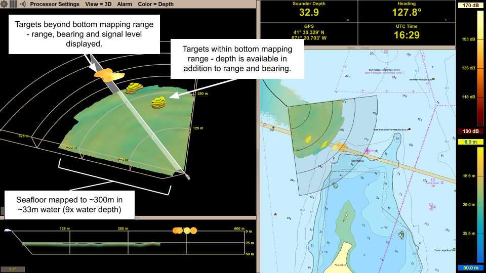
Figure 1 - SonaSoft™ processing and display software showing Argos data while approaching Jamestown Bridge in Narragansett Bay, Rhode Island. The seafloor is mapped out to a range of more than 8 times the depth below the transducer. Detections of potential hazards, or In-water Targets are shown corresponding to the bridge pilings. When within the bottom mapping range, full 3D information is available. While the targets are beyond the bottom mapping range, the range, bearing and signal level are shown.
The full image generated by Argos sonars is refreshed with every ping, avoiding any mechanical scanning or beam steering on transmit. This means the refresh rate can be as fast as 3 times per second in 100m mode to once every 2-3 seconds in 1000m mode. A faster refresh rate of the entire field of view allows human operators, or navigation controller systems depending on Argos data, to operate at faster speeds and obtain a more complete view of the environment more quickly.
Some of the specific navigation situations where realtime 3D FLS data can be used to enhance navigation safety are introduced in a previous blog. The blog focused on cases with human operators, however, inaccurate GPS positioning, uncharted or unforeseen hazards in the water column such as reefs or shipping containers, or inaccurate depth data on nautical charts are all issues that unmanned or autonomous vessels also have to navigate. The availability of some form of real-time data describing the presence of possible navigation hazards and seafloor depths ahead of the vessel is crucial to autonomous systems if they aim to be able to successfully adapt to and navigate the changing and sometimes unpredictable marine environment.
Autonomous systems sometimes try to fill information gaps about seafloor depths ahead of the vessel in an effort to look for the presence of unexpected navigation hazards by gathering data and building images using side scan sonar and echosounders, or by deploying remote or autonomous undersea vessels (Wright, 2020). These methods have their merits, however, unfortunately they do not provide all of the necessary information for safe navigation. As illustrated above, data from a single Argos 3D FLS sonar gives real-time information about both the depth ahead of the vessel, and navigation hazards in the water column. A 3D image of the entire field of view of the sonar is updated with each ping, meaning that the XYZ coordinates of the detected seafloor and / or detected navigational hazards are available in the sonar data. The Argos series of 3D FLS are the only systems capable of generating such a volume of 3D information in front of the vessel, out the long (350-1000m) ranges. This elevated situational awareness is imperative when there is no human operator present.
Figure 1 above shows a screenshot of the SonaSoft™ display, which of course is used by human operators. This is how the 3D sonar detections are displayed for a human operator using an Argos system on the bridge, however in an unmanned or autonomous system, this is not likely the main interface to the Argos data. The availability of the data for consumption by a navigation controller system is critical. FarSounder makes this detection data, including the XYZ coordinates and additional metadata for each detection, available through an API (available with the SonaSoft™ SDK version). Using the API, developers can easily integrate Argos into their navigation controller systems.
Integration with an Argos sonar
FarSounder’s SonaSoft™ SDK has been used to incorporate Argos data into a number of different integrated bridge and ECDIS systems, and for integration into USV navigation systems. A computer connected to the Argos Transducer Module processes and detects the seafloor and navigation hazards in the raw data, and then serves the data for any clients connected.
The process of integration is straightforward and the available example project will make getting Argos data into any navigation controller or other client system easy, so that the developers can focus on incorporating the data into their own decision algorithms. Apart from receiving a 3D point cloud of detected in water targets and seafloor depths from the server, the client can also receive navigation information provided to SonaSoft™ via other sensors, and raw hydrophone data. The latter of which can be used to detect instances of inference of the presence of other environmental factors that may degrade performance, which is useful information for a navigation controller application to pull into their algorithms.
The remainder of this section is a little more technical, and talks about the recommended method of integrating Argos data into any client system. This is for those who want all the technical details.
We recommend the use of ZeroMQ to open a TCP socket on the client and send or receive data to the server. The messages used to communicate between the server running SonaSoft™ and the client are serialized and represented using Protocol Buffers. The data can be communicated to any client from the server using a request / reply or a publish / subscribe approach. Files (.proto) describing the messages that the server can receive, as well as messages that represent the data that the server will produce, and all of their associated TCP ports are provided in the SDK.
Along with those message descriptions, an example project that gives simple but complete examples of how to communicate with the server in both the request / reply and publish / subscribe framework is available.
Finally, more detailed technical information about the SDK and how to integrate Argos data into your navigation controller are available in the Interface Design Definition.
In general, to integrate Argos data, a client application will:
Open a TCP socket (the port number corresponds to the message / data type, and is given in the .proto files).
When sending the server data, for example a request message, first create a Protobuf message with the data that is to be sent to the server and then serialize and send the message on the socket opened in step 1.
When receiving data, the message received from the server is serialized and will need to be parsed into a proto message before the data can be read.
Note that the SDK Example project gives examples of all of these steps in C++.
Finally, the client can control the instance of SonaSoft™ running on the server, so that all of the relevant processing parameters can be adjusted for a specific situation, as needed, based on the controller’s algorithm.
Conclusion
An Argos real-time 3D forward looking sonar system is an excellent tool to improve situational awareness for human operators and navigation control systems alike. Mapping the seafloor depth and detecting navigational hazards out ahead of the vessel to navigationally relevant ranges and with the entire field of view updating with each ping allows the controller more time to respond and to change vessel speed and / or course based on this information.
More information about FarSounder’s Navigation SDK is available here or by contacting us at info@farsounder.com.
To learn more about our systems in general, performance, and expectations, please check out our previous tech blogs. Further, we have recently launched virtual training courses for customers, technicians, and dealers representatives. Visit https://training.farsounder.com to see our current course offerings, and of course, feel free to contact us with any questions.