Installing a Sonar on High Speed Vessels: Problems and Solutions
When considering one of our forward facing navigation or diver detection sonars, customers are often curious about the sonar's impact on the performance of their vessel. Most people are familiar with the general concepts of streamlining with reference to their car. Such effects when operating in air are described by the vehicle's aerodynamics. Similar effects as they relate to ships and boats traveling through water are called hydrodynamics. In this blog posting, we'll be discussing the general concepts that should be considered with evaluating the hydrodynamic impact of a particular installation.
First, let's discuss the concepts in more general terms and keep with the car analogy. To begin with, suppose you want to install some sort of sensor or accessory to the outside body of your vehicle (like a new satellite radio antenna or roof rack for the car). How should it be installed? On an intuitive level, you know it should be streamlined with your vehicle's body and it should be protected from possible damage due to any minor collision. Some questions which arise are:
What really happens if the installation is not streamlined?
If you really need to streamline the installation, how can you do it?
As you may have guessed, these are the exact same questions that should be asked in reference to the installation of any sort of underwater equipment on a boat's hull.
The Basics of Vehicle Aero-/Hydro-Dynamics
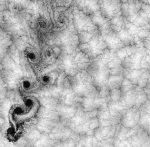
Turbulence as seen from space
In trying to understand the dynamic impact of such features on a body, there are two primary effects to consider. First is the pressure resistance of air flow (for the car or aircraft) or the water flow (for the ship) – actually, in the case of the ship, one must consider the aerodynamics for the structures above the water (like radar masts) as well as the hydrodynamics for structures below the waterline (like bow thrusters, sonars, and cooling systems). This resistance (or pressure drag force) is proportional to the media (air or water) density, vehicle speed, vehicle cross-sectional area, and the drag coefficient. The drag coefficient depends on the vehicle body shape (and surface roughness), but usually it depends on the overall shape without details. So any (even ugly looking) sensor installation is generally acceptable as long as it does not enlarge the cross-sectional area.

Golf ball dimples - using turbulence for good
The second factor is the turbulence. When the vehicle speed is high, part of the flow around the body may be turbulent (not smooth). Turbulence occurs not only around the non-smooth parts of the body but also behind the sharp turns and corners. Turbulent flow sounds bad. However, it is important to note that turbulence is not necessarily a bad thing by itself. In fact, a thin turbulent boundary layer around the body can actually reduce the viscous drag force. This is the reason why there are dimples on a golf ball. The turbulence they create help it fly better.
One effect of turbulence which may have a negative impact is “separated turbulent flow” - a stream of vortices detached from the hull. If such a turbulent stream hits the ship's propeller, it will make the propeller less efficient as well as cause vibrations. This kind of turbulence also reduces vehicle speed, because some part of the engine power is literally flying away with a turbulent separated flow. Separated vortices may be triggered even by the relatively small things (as compared to the entire hull size) sticking out of the hull. As mentioned above, significant turbulence happens at high speeds. From a practical point of view for boats, this means speeds above 20 knots.
Fairings

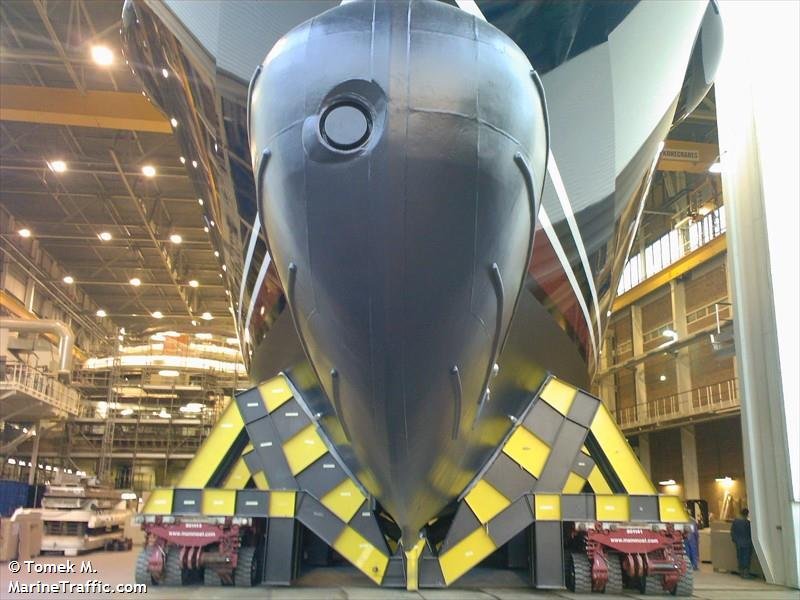
Sonar faired into flat bulkhead
When evaluating a sonar installation, hydrodynamic effects should be considered. The ideal case (from the vessel hydrodynamics point of view) is to have a sonar sensor shape that is perfectly conformal to the original hull shape. Since this is not always possible, the use of a fairing can reduce both pressure resistance and turbulence. This is particularly important for vessels operating at speeds above 20 knots.
A well designed fairing can also provide good protection to the sonar's transducer hardware. When talking about sensor protection, the concern is usually not for protection against catastrophic incidents. Rather it generally refers to protection against minor incidents and standard operational conditions. For a ship or boat, this may mean "What if we touch the pier while docking or the anchor chain comes across our bow when currents or winds shift?" From that point of view, a protective fairing around the sensor can do the job. The fairing can also be designed to improve hydrodynamics, providing a smooth transition shape between the active sensor face and the surrounding part of the hull.
Domes

Radar dome on aircraft
Besides conformal sensor shapes and smooth fairings, a third option for streamlining a sensor installation is to use a dome. A dome is a housing which makes a smooth surface, covering the sensor. An obvious requirement for a good dome design is that the dome material must be transparent to the sensor's signals. Additionally, the dome material must be strong enough to survive standard vessel operations.
It is relatively easy to design a radar dome as radar uses electromagnetic waves for its signals. To be transparent to these waves, the dome material just must be dielectric. Many materials commonly used in fabrication meet this requirement. Often, the elliptical front part of an airplane fuselage is a radar dome, made of thick fiberglass.

Large dome for low frequency sonar
In the case of sonar, it is relatively difficult and expensive to design a dome. The figure at right shows one particular sonar dome for a combat ship made by Goodrich Corp. It is made from a rubber-like material, reinforced with fiberglass threads. So what is the problem with the sonar domes? The answer is that sonar uses sound waves to operate. As such there are a number of issues to consider in the sonar dome design.
Transparency and Lensing

Simple lensing example
Sound propagation is a mechanical process by nature. This means if you want the material to be rigid, it will generally not be transparent to sound waves (especially at the frequencies used by high performance multibeam and forward looking sonars). Transparency and the related reflection coefficients of a material depends on many factors including: material density, sound speed in material, layer thickness, signal frequency and direction of incoming sound wave. A dome material that is transparent for a 3kHz frequency sonar is not at all transparent for a 300kHz sonar.
If the dome material is transparent but thick relative to the signal's wavelength, the rounded fairing could end up acting like a lens and changing the focus of the array. This is like putting on someone else's glasses. In some water conditions the effect may be minimal, but others it may be greater. Lensing effects are hard to predict without in-situ measurements. It is something that can be compensated for in theory but requires a complicated calibration process and modification to the processing software. In extreme cases, the lensing may be so great that the sound waves never actually reach the sonar sensor. In these cases, lensing effects cannot be compensated for.

Example sonar sound field with and without a dome
Additionally, if the sonar dome is not perfectly transparent more issues can arise. Assume for the moment that you have a dome which is 90% acoustically transparent. What happens to the 10% of sound energy which is reflected internally and gets trapped inside the dome? These reflected signals will start bouncing between the active sonar surface and the dome. This creates a sound intensity distribution with a number of peaks and nulls. The sonar will see these peaks as a series of false targets. The figure at right illustrates this effect with an example sound field in front of a sonar transducer with and without an example dome which is mostly (but not completely) transparent. In this particular example, a very thin (1mm) composite material was used and still there were some negative effects.
Attenuation
Besides, passing or reflecting sonar energy, the dome material may also absorb energy. This process is called attenuation and is the effect of converting the acoustic energy into heat energy. The amount of attenuation is a function of the material's properties as well as the material's thickness. This is one more reason to keep the dome thin. However, this is again at odds with the mechanical needs of the dome. Even with the best materials, there may be 2-3 dB of attenuation. This would result in a reduction in maximum range of about 5-10%.
Biological Fouling

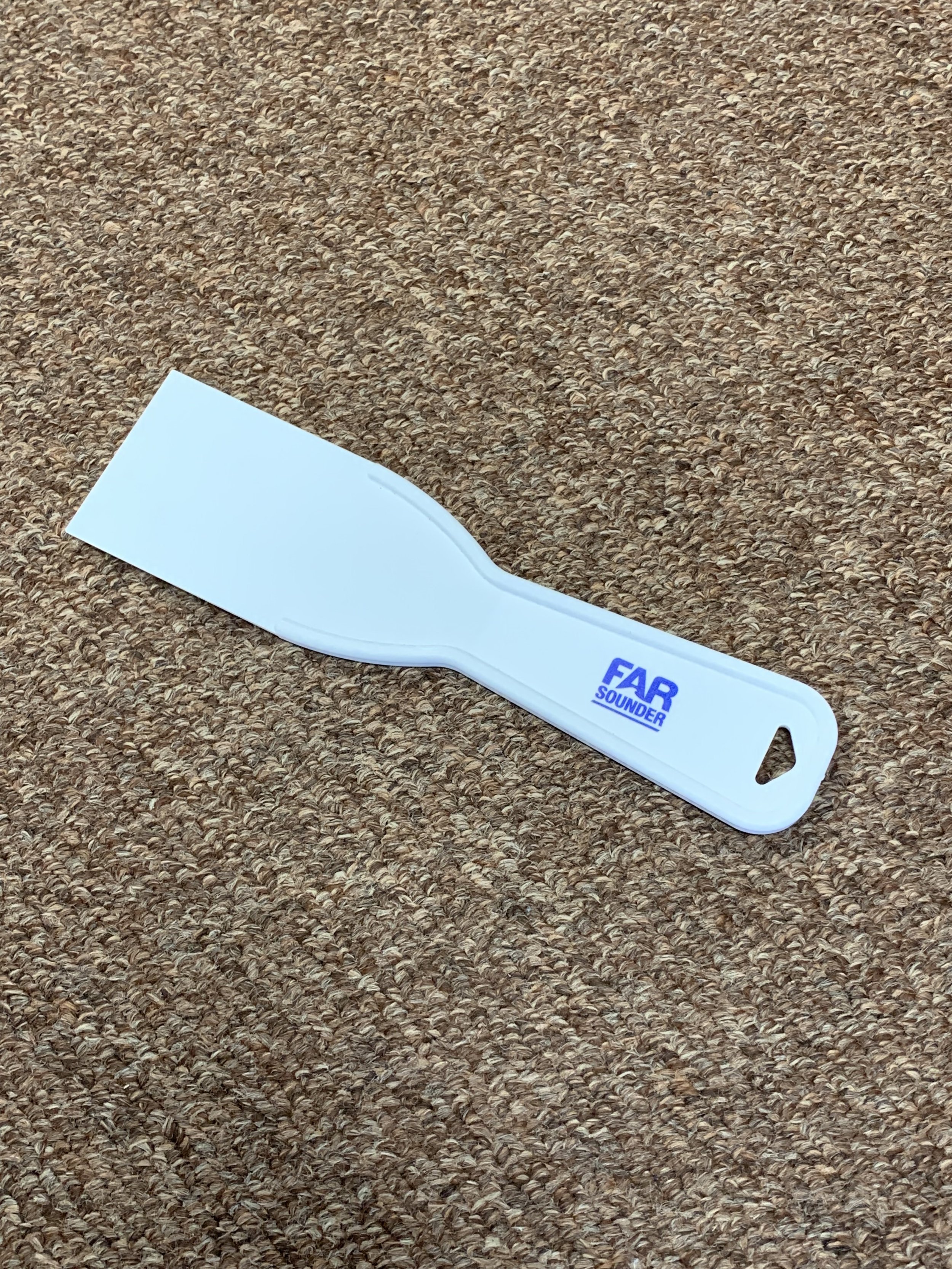
Biological fouling can affect sound waves
Just as the sonar transmits sound into the water in the case of a no sonar dome installation, the sonar must be submerged in water inside the sonar dome. This allows the sound waves to propagate from the sonar to the dome and on to the open water. This probably means there is an opening to the ambient water to ensure the dome is fully filled. In this case, just like the outside of the rounded fairing, the inside may experience biological fouling which will impact the system's performance. Biological fouling can have a large impact on sonar performance. Normally, echo sounders and other exposed sonars can be cleaned by a diver and a simple scraping tool. Unlike fouling on the outside, it will be difficult to see or clean fouling inside the dome. Even if there are no openings and the water inside the dome is separated from the external water, periodic cleaning and re-filling may still be needed.
Read more about FarSounder’s recommendations to keep your sonar clean.
Overall, the development and manufacturing of the sonar dome is a highly complicated task which requires close coordination between naval architects, acoustical engineers and sonar system designers. Due to the strict acoustic requirements and the close manufacturing tolerances, the fabrication of sonar domes can also be a challenge. For the above reasons, sonar domes are often cost prohibitive and few sonars other than large, expensive, low-frequency military sonars use sonar domes. In these cases, the costs can be amortized across multiple vessels as most military sonars and ships are built in quantity with the exact same hull designs for a given vessel class.
FarSounder Sonar Installation
In the case of FarSounder sonars, a simple fairing is generally all that is needed for an effective installation solution. FarSounder provides an Installation Design Guide to parties involved with an installation design. This guide provides detailed recommendations on how best to fit the Transducer Module to the ship's hull using a fairing. We offer a complimentary installation drawing review service and recommend working with our engineers to ensure your installation is optimal.
For more information about the fitting a FarSounder sonar to an existing vessel or vessel design, please see our blog posts about installation. A variety of installation examples can found in our Installation Gallery.