Explaining the Water Depth Limit and Other Unexpected Reflections
Not all forward looking sonars are created equal. Most only produce a view of a single 2 dimensional slice. Some use scanning technology to build an image from multiple pings. Few employ 3D technology. FarSounder sonars are the only look-ahead sonars which produce a true 3-dimensional image at navigationally significant ranges. They do this with a single ping enabling a fast update rate. Clearly, range is an important metric. However, one number alone cannot fully describe a sonar's range capabilities. A navigation sonar should specify its range not only in terms of maximum detection range for a given in-water target size, but also maximum range at which it can map the bottom. The first range metric is a number that is easy to specify given a target's reflectivity (e.g Target Strength) in a nominal marine environment. The second number is more difficult because it is not fixed. Rather, the bottom mapping range of a forward looking sonar is primarily a function of the water depth below the transducer. This blog posting explains what drives this limit and how these same concepts can explain other “unexpected” echo reflections.
Simple Down-Looking Sonars

Reflections from an echosounder
In the case of echo sounders, the transducer is oriented such that it points roughly straight down. These sonars transmit a signal and listen for the echo off the seafloor. When transmitting in this orientation, the sound waves are pointed directly towards the sea floor. A small portion of the energy is scattered in various directions due to the roughness of the sea floor (sand, rocks, debris, coral, etc.), and a small portion of the energy is absorbed by the sea floor material (more in the case of a soft mud, less in the case of a hard sand). However, because of the perpendicular orientation of the incoming sound waves, the resulting echo's sound waves reflect back at almost the same angle. The sea floor is acting as a moderately efficient acoustic mirror. This is illustrated in the first image at right.
Projecting Sound Waves Forward

Steep angle reflections

Medium angle reflections
Forward looking sonars, by definition, send much of their transmitted energy forward with varying downward (and/or upward) angles. When the down angles are steep with much of the energy pointed towards the sea floor, a large percentage of the energy is reflected back to the sonar's receiver, though some of the energy is reflected forward just like light bouncing off a glass mirror. The energy bouncing back to the sonar is aptly called “back-scatter” while the energy bouncing forward is called “forward-scatter”.

Shallow angle reflections
As the down angle becomes more shallow, the amount of back-scatter decreases as the forward-scatter increases. The actual ratio of back-scatter to forward-scatter for a given angle varies slightly with sea bottom composition. If the sea floor is rough, relative to the size of the acoustic wavelength, then there are more “edges” on the seafloor that are reflecting back towards the sonar. If the sea floor is comparatively smooth, then the sea floor acts more like a true reflecting mirror. The next few images at right illustrate this point. In reality, the situation is actually quite a bit more complicated as the sound waves reflect no only off the seafloor but also off the sea surface - sometimes more than once! This type of bouncing is called multipath propagation. This effect was discussed a bit in our tech blog posting about sonar performance prediction.

Multipath reflections
Differing levels of sophistication enable various navigation sonar products to extract back-scatter reflections from the sea floor at differing minimum echo levels. This directly defines the water depth limit at which a particular sonar can produce bottom maps ahead of the vessel. Our Argos navigation sonar products are specified as 8 water depth sonars. This means they can map the seafloor out to a range equal to 8 times the depth below the transducer. Depending on the actual local propagation conditions and the sea floor composition, this range may be longer or slightly shorter. Our screenshot gallery shows a wide selection of locations and environments with this type of bottom mapping. When evaluating other sonar products, be sure to note the water depth ratio of their bottom mapping ranges. FarSounder is a leader in this capability.
Detecting In-Water Targets Beyond the Water Depth Limit
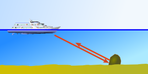
Shallow angle reflections with in-water target
As mentioned previously, a sonar's bottom mapping range limit is not the same as its maximum detection range. This seems obvious for objects floating in the middle of the water column. However, even obstacles laying on the seafloor can reflect well beyond the bottom mapping limit. To illustrate this case, consider a rock on the sea floor as shown in the figure at right. The rock creates a reflecting surface that is able to angle the reflected signals back to the sonar rather than forward-scattering them away from the sonar. It may not be possible to tell the exact depth of that obstacle, but it can be clearly detected as an in-water target.
The ability to detect obstacles beyond a sonar's water depth limit is extremely important. Vessel operators can detect the edge of rock ledges, shore lines, submerged coral reefs, and other navigation hazards. This is helpful even in charted areas. For example, charts often mark an area as “reef” or “rocks” but don't give the exact locations. Sometimes channel markers are missing or have moved from their nominal locations on the chart. The sonar can help the vessel operator know exactly where their ship is located relative to the edge of the channel.
Understanding “Stealth” Targets

Approaching "stealth" vessel target from side
The concepts above are easy to understand with simple physics. They may even seem obvious once explained. However, sometimes a target that a user might expect to be big appears small or is not detected at all. For example, sonars often have trouble detecting large vessels. Radars can detect them well at almost any orientation, yet to be detectable with a sonar, they must be in particular orientations. Though less intuitive, this effect can be explained with the same physics as above.

Approaching vessel ahead
Consider the case when a vessel with an obstacle avoidance navigation sonar approaches another large, anchored ship. Since the hull under the water is very smooth compared to the wavelength of the sonar, it will act as a very effective acoustic mirror. This is not the case with the portion of the ship above the water. There are lots of features and structures which reflect back to the radar. If the approach is from the side, and the angle to the vessel is shallow, the smooth hull of the ship will reflect nearly all of the sonar's energy at an angle that won't return to the sonar's receiver. If the approach is angled such that the ship is exactly tangent to a sonar range ring, then the ship should be detectable. Unless the vessel is approached broadside, the vessel may only be tangentially aligned for 1 or 2 pings. The final two figures at right illustrate this concept. It is very difficult to detect a ship with a sonar when approaching head on. If the target vessel is moving, then the bubbles from the wake generally make good sonar targets and may be detected even if the hull is not.